Generic 1C10 5V Two 2 Channel Relay Module With optocoupler
20.00
AED
(incl. VAT)
Free shipping & Delivery
Estimated delivery:
Trendyol's commitments
Shopping security
Secure payment
Privacy protection
Safe delivery
Refund for lost and damaged packages
Coupon for late delivery
Free returns
Easy and free return in 15 days.
Highlighted features:
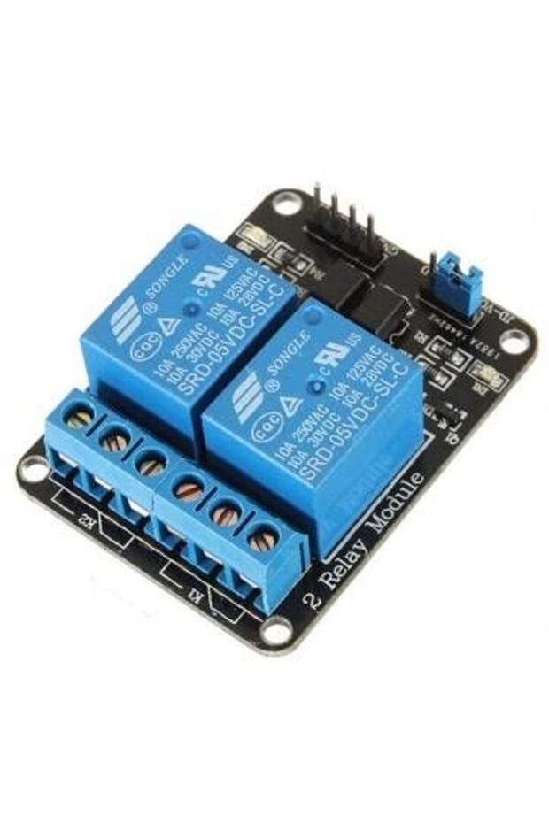
Generic 1C10 5V Two 2 Channel Relay Module With optocoupler features
Other Features
Optocoupler, LED status indicator, Screw terminals, Digital output controllable, TTL level control signal, Power supply isolation option
Instructions for Use/Warnings
Warning: This board interacts with HIGH AC voltage. Improper or incorrect use could result in serious injury or death. Therefore, it is intended for people who are familiar with and knowledgeable about HIGH AC voltage. Instructions for wiring: Connect module's VCC pin to the Arduino's 5V pin and the GND pin to ground. Connect a digital pin (e.g., #6) to an IN input pin (e.g., IN1). To control an AC-powered device, cut the live AC line; connect one end of the cut wire (coming from the wall) to COM and the other to NC (normally closed/on) or NO (normally open/off) depending on the desired initial state. For physical isolation, remove the jumper and provide a separate 5V power supply to JD-VCC and GND.
Product details

Generic 1C10 5V Two 2 Channel Relay Module With optocoupler features
Other Features
Optocoupler, LED status indicator, Screw terminals, Digital output controllable, TTL level control signal, Power supply isolation option
Instructions for Use/Warnings
Warning: This board interacts with HIGH AC voltage. Improper or incorrect use could result in serious injury or death. Therefore, it is intended for people who are familiar with and knowledgeable about HIGH AC voltage. Instructions for wiring: Connect module's VCC pin to the Arduino's 5V pin and the GND pin to ground. Connect a digital pin (e.g., #6) to an IN input pin (e.g., IN1). To control an AC-powered device, cut the live AC line; connect one end of the cut wire (coming from the wall) to COM and the other to NC (normally closed/on) or NO (normally open/off) depending on the desired initial state. For physical isolation, remove the jumper and provide a separate 5V power supply to JD-VCC and GND.
Safety information
Product safety information